Tiny electronic dice
TinyDice is a tiny (35mm * 17mm) electronic dice powered by ATtiny13A.
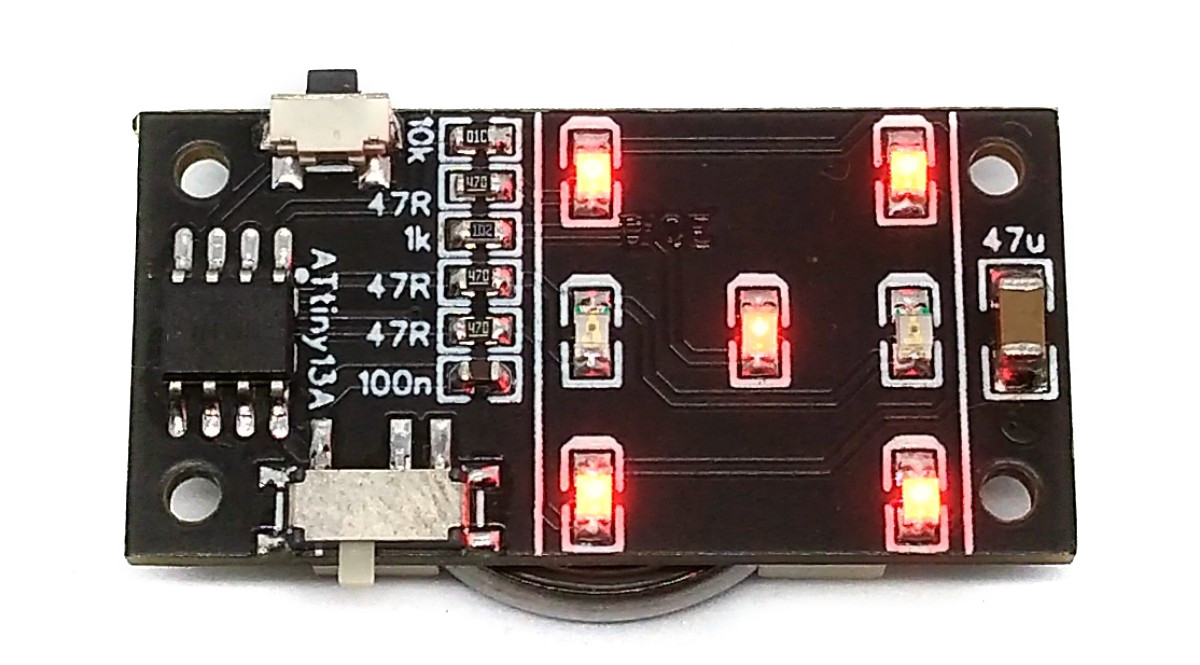
The wiring is pretty simple:
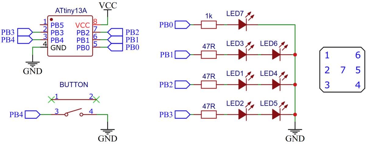
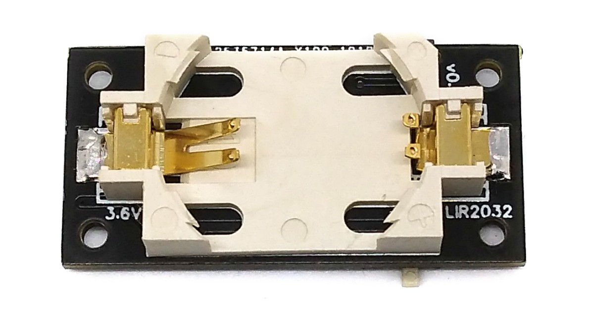
The fact that the opposite pairs of dots on a dice always appear together was used for the circuit diagram. This means that there is no need for Multi or Charlieplexing. However, the supply voltage must be at least twice as high as the forward voltage of the LEDs. Therefore only red LEDs and the rechargeable LIR2032 li-ion batteries should be used.
Timer0 is used to constantly change the number of pips in the background. Chance is created by the uncertainty of the moment the button is pressed by the user, which brings the current number of pips to display. As long as nothing else needs to be done, the ATtiny remains in IDLE and only wakes up when you press a button (pin change interrupt). Then it rolls the dice, in which a series of numbers are shown on the dice with increasing time interval. Finally, the last number shown remains and the ATtiny changes back to IDLE. The number of pips shown on the dice corresponds to the respective variable pips, which is constantly changed by the timer overflow interrupt. A simple matrix is used to control the LEDs, with which the respective number is converted into the values for the PORTB register.
// Libraries#include <avr/io.h> // for GPIO#include <avr/sleep.h> // for sleep mode#include <avr/interrupt.h> // for interrupts#include <util/delay.h> // for delays// Global variablesvolatile uint8_t pips = 0; // current number of pips// Main functionint main(void) {// Local variablesuint8_t matrix[] = {0b00110001, // 10b00110100, // 20b00110011, // 30b00110110, // 40b00110111, // 50b00111110};// 6 - for converting pips to pins// Setup pinsDDRB = 0b00001111; // PB0 - PB3 as output, PB4 inputPORTB = 0b00110001; // pull-up for PB4/5; LED7 on// Setup timer/counterTCCR0A = 0b00000000; // no outputTCCR0B = 0b00000011; // set prescaler to 64TIMSK0 = 0b00000010; // enable timer overflow interrupt// Setup pin change interruptGIMSK = 0b00100000; // turn on pin change interruptsPCMSK = 0b00010000; // pin change interrupt on button pinSREG |= 0b10000000; // enable global interrupts// Disable unused peripherals and set sleep mode to save powerACSR = 0b10000000; // disable analog comperatorPRR = 0b00000001; // shut down ADCset_sleep_mode(SLEEP_MODE_IDLE);// set sleep mode to IDLE// Loopwhile(1) {sleep_mode(); // go to sleepif(~PINB & 0b00010000) { // if button pressed:for(uint8_t i = 0; i < 16; i++) { // roll the diceuint8_t del = (i << 4); // increasing delay between pip-showswhile(del--) _delay_ms(1); // set the delayPORTB = matrix[pips]; // show current number of pips}while(~PINB & 0b00010000); // wait for button released_delay_ms(10); // debounce}}}// Timer0 overflow interrupt service routineISR(TIM0_OVF_vect) {if(++pips > 5) pips = 0; // cycle number of pips on every timer overflow}// Pin change interrupt service routineEMPTY_INTERRUPT(PCINT0_vect); // nothing to be done here, just wake up from sleep
Since there is no ICSP header on the board, you have to program the ATtiny either before soldering using an SOP adapter, or after soldering using an EEPROM clip. The AVR Programmer Adapter can help with this.
avrdude -c usbasp -p t13 -U lfuse0x2a:m -U hfuse
PROGRMR=usbasp make install to compile, burn the fuses and upload the firmware (change PROGRMR accordingly).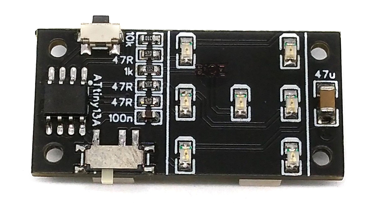

This work is licensed under Creative Commons Attribution-ShareAlike 3.0 Unported License.
(http://creativecommons.org/licenses/by-sa/3.0/)