LoRa-E5 Tiny cell coin STM32WL LoRaWAN board

Based on LoRa-E5 from Seedstudio, but I wanted something really Tiny so I removed loy of stuff and left only JTAG prog, Serial and I2C Stemma QWIIC connector, and of course cell coin handler.
take a look on this excellent reading on how to use capacitor to prolong cell coin batteries and understand the risk. I will use for EU8868 so for peaks approx 40mA, 3 times less than in the article so I guess it could works with 2 x 220uF or 470uF capacitors. Challenge would be to find them in 1206 footprint format.
I’m using mainly to flash custom firmware in it, and not using AT default firmware.
These boards have been received they works as expected but stil not tried with cell coin powering
With this consumption issue discovered on LoRa-E5 boards (but also on RAK3172) I’m not confident it will works on Cell Coin CR2450 battery even if I added 2 330uF capacitors on 3.3V rail.
use 3.3V FTDI One, not 5V)No specific documentation for now, it’s just a kind of wiring helper as schematic.
I also assume that you are familiar with all LoRaWAN stuff, all setup/infrastructure/network server/provisionning and other are out of scope of this repository.

You can order board on oshpark.
It’s a pitty after several discuss with OSHPark that I can’t have any rewards for each people ordering my boards, this would allow me to order free PCB for shared projects and create new ones. For information my shared boards generated a total of $285 162.00 orders at PCBs.io in 4 years, not bad at all :-), but looks like they have gone 
Hoping one day OSHparks will thanks me giving them this market.
Top & bottom side V1.0

Nothing fancy, due to size constraint, components are 0603/1206 and can be ordered almost anywhere (digikey, mouser, radiospare, …).
use only what you need dependings on what you want to do.
I2C pullup may not needed, most QWIIC/Steamma boards have their own.
Check Seeed format BOM File, check on Seeed OPL for manufacturer SKU match.
When the boards are from factory, default AT firmware is flashed and thus we have the possibility to test the board before flashing custom firmware and maily also get defaults keys from device.
To do so, connect a 3V3 FTDI Type USB/Serial to access Serial Console
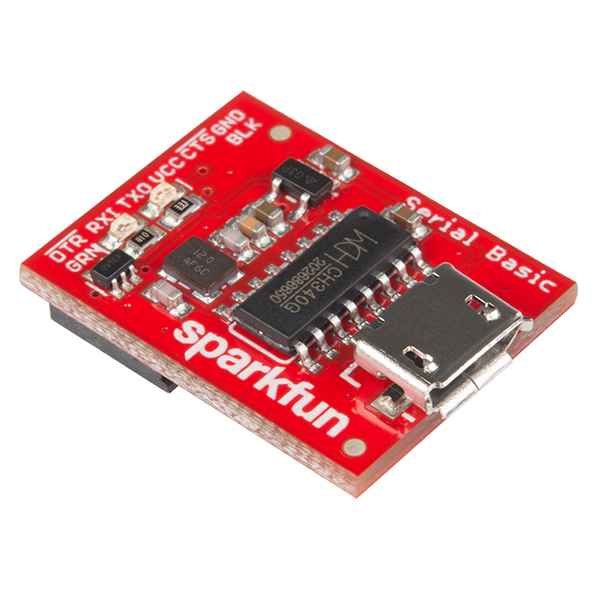
I personnaly use these one for Sparkun but you can find clones anywhere on the Web.
Once done open Serial terminal (the one from FTDI Serial Port) configured as 9600 BPS 8N1, no flow control, echo typed characters and set to CR+LF for enter key, press reset button and you should be able to see banner
Once done open Serial terminal (the one from FTDI Serial Port) configured as 9600 BPS 8N1, no flow control, echo typed characters and set to CR+LF for enter key
Then type AT command to see if the LoRa board answer, in this example the board answered +AT: OK which is correct
AT+AT: OK
Now get the device version
AT+VER+VER: 4.0.11
Now get the device information
AT+ID+ID: DevAddr, 24:90:08:93+ID: DevEui, 2C:F7:F1:20:24:90:08:93+ID: AppEui, 80:00:00:00:00:00:00:06
I’m using TTN for testing so please follow excellent RAK guide on how to provision your device onto TTN here
In our case we will use the AppKey generated from TTN when provisionning device, just provision your device onto TTN, get the key and put into the device as follow with command AT+KEY=APPKEY in our case AppKey is B7536DCEFB1EBC4AB9871293F6FA7DB5
AT+KEY=APPKEY,"B7536DCEFB1EBC4AB9871293F6FA7DB5"+KEY: APPKEY B7536DCEFB1EBC4AB9871293F6FA7DB5
Set ADR + Frequency Plan EU868 + OTAA
AT+ADR=ON+ADR: ONAT+DR=EU868+DR: EU868AT+MODE=LWOTAA+MODE: LWOTAA
Check Frequency Plan
AT+DR=SCHEME+DR: EU868+DR: EU868 DR0 SF12 BW125K+DR: EU868 DR1 SF11 BW125K+DR: EU868 DR2 SF10 BW125K+DR: EU868 DR3 SF9 BW125K+DR: EU868 DR4 SF8 BW125K+DR: EU868 DR5 SF7 BW125K+DR: EU868 DR6 SF7 BW250K+DR: EU868 DR7 FSK 50kbps+DR: EU868 DR8 RFU+DR: EU868 DR9 RFU+DR: EU868 DR10 RFU+DR: EU868 DR11 RFU+DR: EU868 DR12 RFU+DR: EU868 DR13 RFU+DR: EU868 DR14 RFU+DR: EU868 DR15 RFU
Now time to join (be sure device is provisioned on TTN and you have a TTN gateway around)
AT+JOIN+JOIN: Start+JOIN: NORMAL+JOIN: Network joined+JOIN: NetID 000013 DevAddr 26:0B:63:94+JOIN: Done
Now send confirmed Hello World message
AT+CMSG="Hello World"+CMSG: Start+CMSG: Wait ACK+CMSG: FPENDING+CMSG: ACK Received+CMSG: RXWIN1, RSSI -40, SNR 5.0+CMSG: Done
You can flash the board with excellent mbed-os framework.
Easy way is to use mbed studio IDE.
We added this board into stm32customtargets, don’t hesitate to read the readme.
Finally the main firmware mbed-os-example-lorawan program.
Once IDE installed:
file / import program and them import the example with URL https://github.com/ARMmbed/mbed-os-example-lorawanAdd Library and enter https://github.com/ARMmbed/stm32customtargetscustom_targets.json from folder stm32customtargets and copy whole contentscustom_targets.json (yes replace the whole file) mbed_app.json and change parameters on the section target_overrideslora.device-eui, lora.application-eui and lora.application-keymbed_app.json.
"LORA_E5_TINY": {"stm32wl-lora-driver.rf_switch_config": 2,"stm32wl-lora-driver.debug_rx": "LED1","stm32wl-lora-driver.debug_tx": "LED2","stm32wl-lora-driver.debug_invert": 1}
Then on IDE select target “LORA_E5_TINY”, build and flash with your favorite programmer (I’m using STLink) with GND/SWDIO/SWDCLK/RESET connected.
Pay attention, that 1st time you need to erase SeeeStudio original firmware, make sure the Read Out Protection of the device is AA. If it is shown as BB, select AA and click Apply. See the end of this section on how to do that with STM32CubeProgrammer.
From IDE you can build the example. If you plug your STLink while project opened, mbed ide will ask you if you want to set it up for this project/target, once approved you can compile, flash and even debug from mbed ide (need some tools installed, read, very nice.
You can also see logs with the FTDI adapter and any Serial terminal set to 115200 bauds 8 bits no parity 1 stop bit (8N1)
Mbed LoRaWANStack initializedCONFIRMED message retries : 3Adaptive data rate (ADR) - EnabledConnection - In Progress ...Connection - SuccessfulDummy Sensor Value = 323 bytes scheduled for transmissionMessage Sent to Network ServerDummy Sensor Value = 523 bytes scheduled for transmissionMessage Sent to Network ServerDummy Sensor Value = 723 bytes scheduled for transmission
Green LED will be on when on receive mode and Red when sending data.

This work is licensed under a Creative Commons Attribution-NonCommercial 4.0 International License